Beechcraft Super King Air B200 Project
Building the Plugs - Part 2
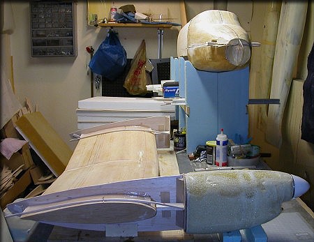
The nacelle/wing alignment problem...
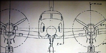
Take a look at the image above, and think about the alignment issues that need to be solved...
On this model, the rear section of the nacelle will be molded along with the wing. The wing has a healthy amount of dihedral, yet the nacelles must be mounted vertically. That means that the wings pass through the nacelles lower inboard and higher outboard. The wing also has washout built-in, which complicates the matter, and so you must insure that the up/down "incidence" of the nacelle is correct, regardless of the wing's incidence at that point. As a scratch builder, you have to figure these things out yourself, because there is no "kit". These are fairly common issue on multi-engine airplanes. These parts are going to be used as plugs for molds, so the alignment must be right. There won't be any way to fix it later. The nacelle construction in going to take a while, and so once the basic structure is aligned, I want it to stay that way during the whole process. I also wanted to make the entire assembly portable, so I can move it around my shop from time to time. My solution was to build a jig, and once I gave it enough thought, I realized that it's really pretty simple.
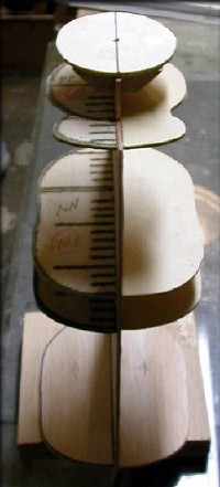
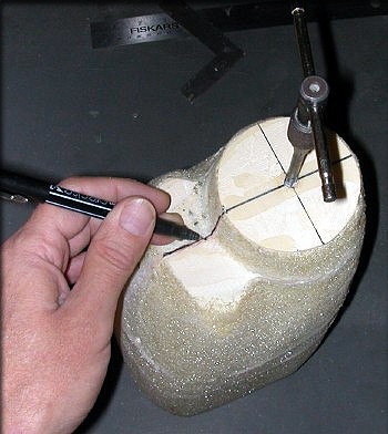
The first item to measure is the distance from the centerline of one nacelle to the other, which you get from the front or top view. I used a balsa building board as the temporary home for this structure, and drew lines at the proper distance, directly on the board denoting where the nacelle centerlines would be.
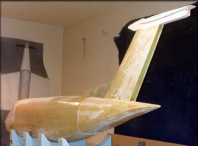
The next number you need is the wing chord, at the centerline point of the nacelles, which you can get from the top view. With this number in hand, I printed out two items. First, I plotted an airfoil of the appropriate chord. Next, I printed out two copies of the side view of the nacelle. On my original drawings, I had already made a point of showing the airfoil incidence relative to both the inboard and outboard edges of the nacelles, so finding the incidence of the "nacelle center" airfoil was easy. Finally, I cut out the airfoil shape from the nacelle side views, so I could slip them onto the wing. I glued these nacelle keels to some 1/8" balsa, cut them out, and then glued some tabs to the bottom of each piece, making sure that they were identical. When you slip them onto the wing. they look like the image below. Don't glue anything yet!
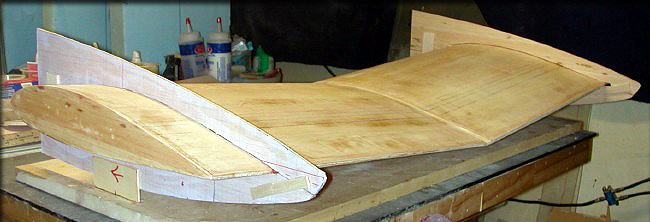
Before gluing anything, there are a few alignment issues to square away. See below.
|
|
|
|
|
|
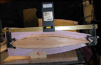
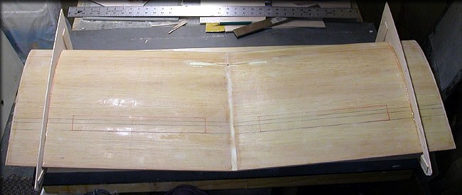
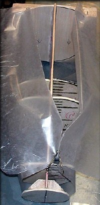
Here's the jig. After checking all the above measurements. I glued the bottom tabs to the balsa board, and glued the nacelle keels to the wing with some thick CA. Now I can relax during the rest of the nacelle building, because I know the alignment is fixed and will not move. Bonus... I can pick this whole assembly up and move it if needed, without disturbing it.
Cowling Plug Construction
I worked out the nacelle design on the wing center section and nacelles so that, although the nacelle rear sections have to be built as "left" and "right", (See below) the front part of the nacelles (the "cowling") can be built from a single plug. This saves work, and also guarantees that both cowlings are exactly the same, since they'll both be made from the same mold.
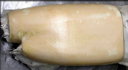
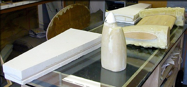
To make the cowling plug, I used a method that's worked well for me in the past, using a mix-and-pour urethan foam to create the basic shape. The advantage, aside from speed and ease of use, is that it makes the plugs very durable... more so than a wooden frame with planking. These will be glassed afterward, further improving their durability. I'll wait until the first cowling is actually molded, before making the inlet duct, to insure a perfect fit.
|
|
|
|
|
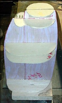
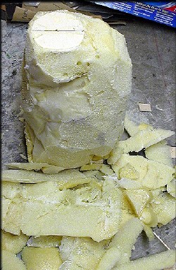
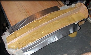
First, I poured in just enough foam to stabilize the structure and form a "floor". This keeps excessive heat or pressure from the foam expansion from distorting any of the formers. After giving this a few minutes to set up, I poured enough extra foam into the form to intentionally overflow. It's very easy to carve away the excess foam once it's cured. For now, total coverage of all the formers is the goal. Neatness is not important at this stage. |
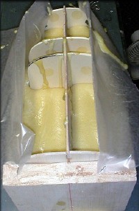
The waxed paper can be pulled off later, or simply carved away, in the shaping process.
|
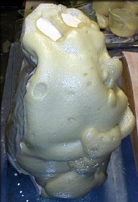
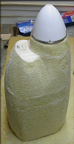
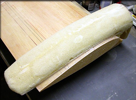
After the foam was poured into the cowling form, (See below) and allowed to overflow, this is what you have. Although this looks horrible, remember... it's only foam, and very easy to carve and sand. I always let these things sit overnight, to be sure it's fully cured. You'll hear it "crackle" occasionally. When it stops crackling for at least a couple of hours, it's done. |
|
|
|
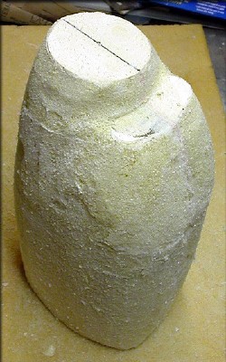
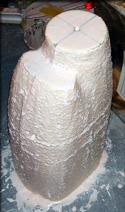
Achieving the shape in the last two images only took about 20 minutes. The next step, after a little more shaping, will be to coat the plug with epoxy and microballoons, followed by normal fiberglassing. Now you see why I made all the formers 1/8" smaller than needed for the final shape. |
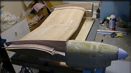
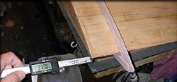
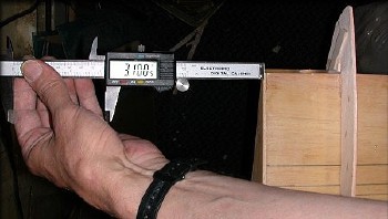
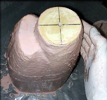
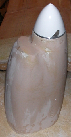
This assembly is larger than it looks. (That's a 3" spinner.)
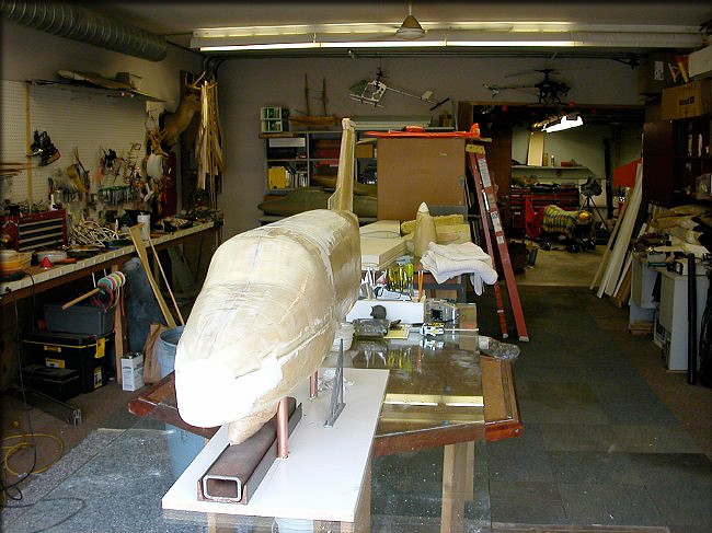
The distance from the nacelle rear edge to the spinner tip is a little over 34 inches.
Here's the cowling plug propped up on blocks, which shows how far forward the engines are mounted.
Really starting to look right now, with the spinner test-fit.
|
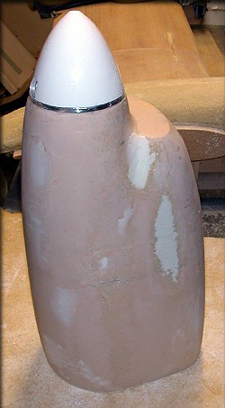
The cowling plug is propped up on blocks to show it's future position. |
|
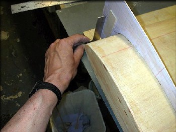
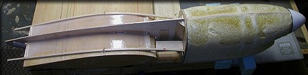
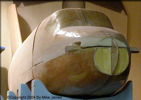
After mounting the nacelle keels, I drew the nacelle outline directly on the wing. Sticks were then pinned to the wing, so that their inside edges are right up against the scale outline. Then, a layer of epoxy and micro-balloons was added between the sticks.The sticks are only pinned down, not glued, and will be removed, once the epoxy has cured. ...So, why did I do this? I'll be using relatively soft materials such as balsa and foam to initially build up the surface of the nacelles on the wing. The layer of epoxy and microballoons provides a precise, tough edge, along with a different color, which will insure that I build the nacelles within the scale outlines. |
|
|
You can see that the keel and formers are "poking out" of the surface. That's intentional, since the formers were cut with an allowance for 1/8" of surface buildup. After the second fill coat and fiberglassing, the surface will expand beyond the formers. |
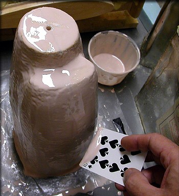
Alignment and SymmetryI'm doing several things on the King Air to insure that those items that there are two of, such as the engine nacelles, are the same. I'll shape the right nacelle first, check it against my drawings for accuracy, and then use those patterns to verify the shape when I make the left nacelle. Both engine cowlings will be made from the same plug/mold, so the symmetry of those parts is guaranteed. (photo at right) |
|
|
|
|

|
|
|
|
|
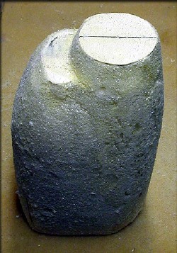
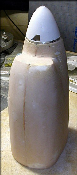
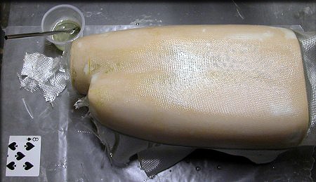
The cowling plug is nearly ready for a little filler, and the final glassing. The surface here is a very tough epoxy-microballons mixture. |
|
After some filling and sanding, the cowling plug is dimensionally back to the level of the keel and formers, but has a hard surface. Next, I'll glass it for durability, and finalize the shape. This plug will be used to double-check both nacelles, which are coming next... |
|
|
|
|
|
|
|
A rolled up piece of waxed paper keeps resin out of the hole already threaded for the spinner backplate bolt. Gravity will flatten out the spinner/intake area as it cures. After final shaping, I'll use it to create matches at the nacelle joints. |
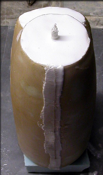
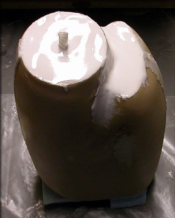 After the glass was cured on both halves of the cowling plug, I trimmed the edges, and applied a thick paste of epoxy and microballoons to the seams and to the spinner/intake area.
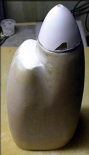
Just a little final shaping, and this part is ready for Paul!
All the fuselage plug parts have now been glassed rather heavily.
While waiting on some supplies for the wings, I've been refining the nose section a little.
During the King Air build, I moved from Anchorage, Alaska, to Charlotte, North Carolina, to join forces with another partner. (I'm now back in Anchorage.)
Outer wing panels are about to be glassed, the cowling plug is nearly ready for detailing.
Click the "The Plugs 03" link below to continue.