Beechcraft Super King Air B200 Project
Building the Plugs - Part 1
* Remember, as you look at these methods. These are plugs for molds, and not for actual flying parts.
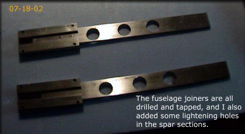
We're using "wing joiner" hardware to keep the fuselage parts aligned.
Here, I've drilled and tapped them, and removed some of the dead weight.
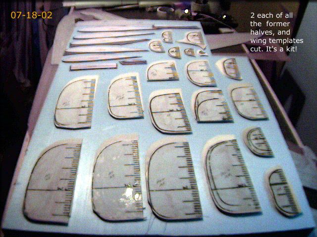
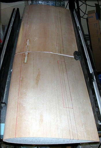
2-part bulkheads and formers were cut from 1/8-inch lite ply, for assembly to the keels.
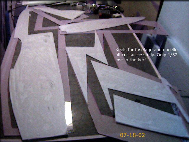
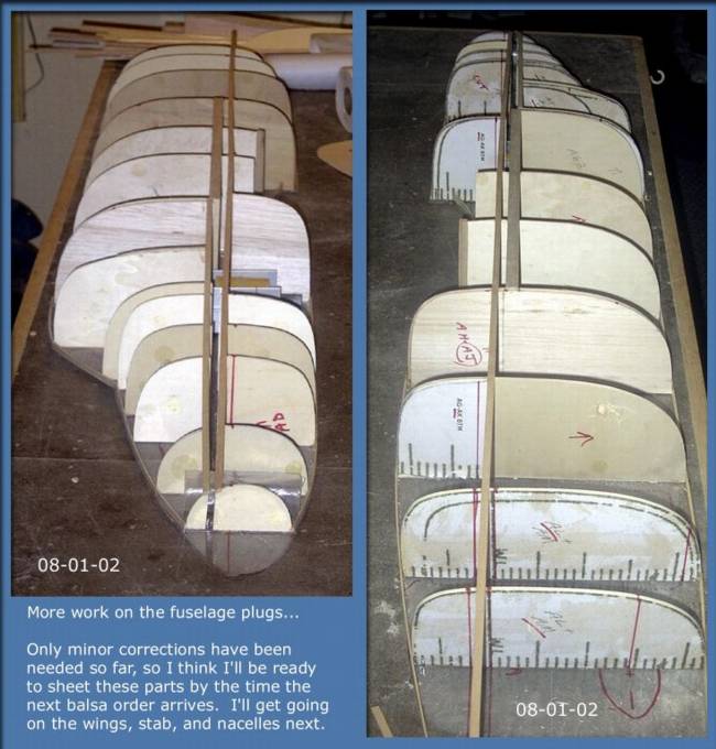
The keels are cut, and I'm about to start assembly of the plugs
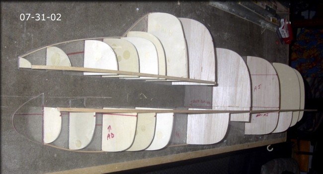
I've started the assembly of the fuselage plugs.
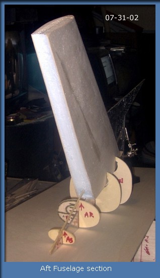
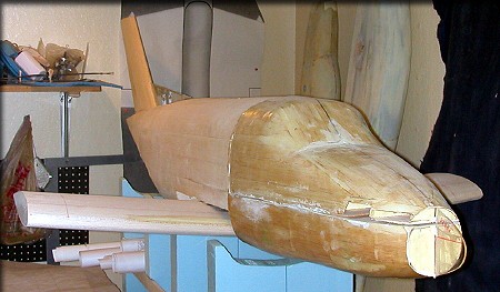
The plug-in aft fuselage section
Starting to sheet the fuselage plugs now...
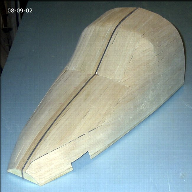
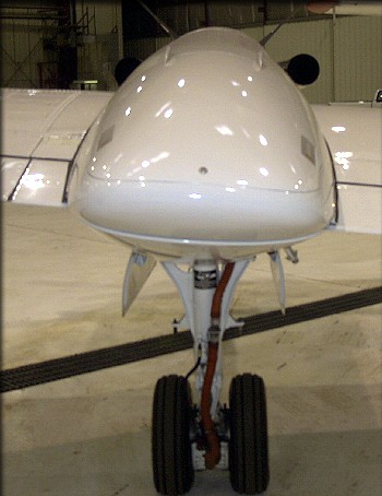
08-09-02 - Both sides of the nose hatch are sheeted
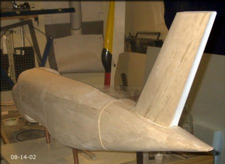
08-14-02 - Both sides of tail cone sheeted. Right side of fuselage remains.
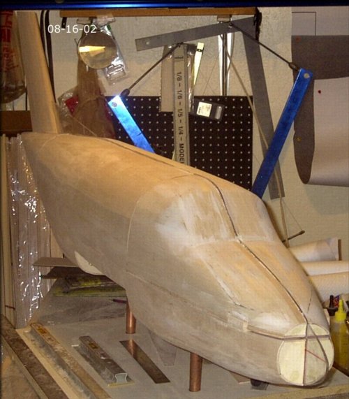
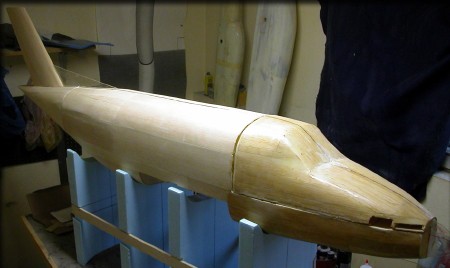
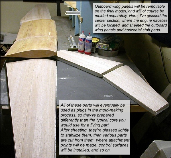
08-16-02 - All fuselage parts are now sheeted. Wings, stabilizer, and nacelles are next.
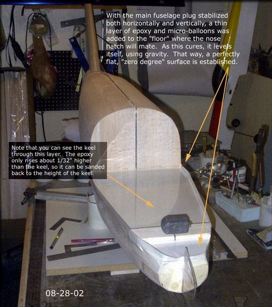
08-28-02 - I'm using gravity to insure that all hatch faces are exactly in line with the internal reference lines in the main fuselage. Later, this makes the mounting and alignment of wings, tail surfaces, and engines very easy, since all the builder has to do is place a level on one of the hatch flanges, and use that reference to level the fuselage.
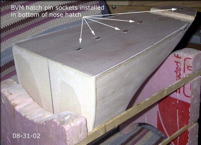
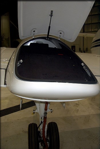
08-31-02 - Here are the sockets in the nose hatch floor.
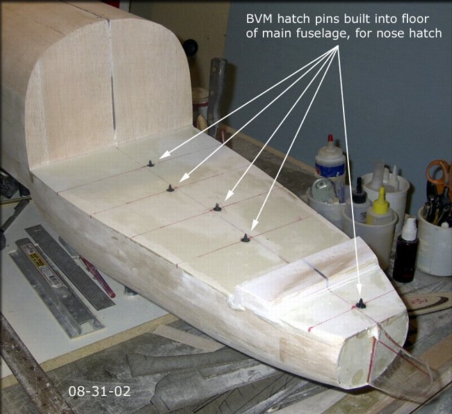
08-31-02 - To keep the nose hatch aligned during plug assembly, sanding, glassing, and final finish, I've installed BVM hatch pins in the main fuselage section. These insert into BVM hatch pin sockets in the bottom of the nose hatch. (below)
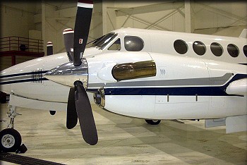
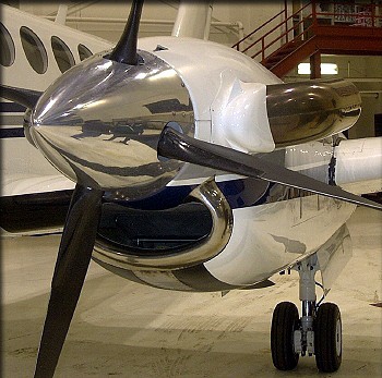
As of August 24th, 2003, work has resumed on the B200 project! Here a couple of photos.
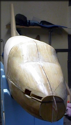
The nose hatch area looks a little darker than the fuselage, because it's been glassed.
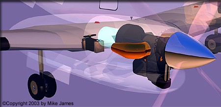
Looking at our 3D model gives you an idea of where some of the RC parts will go in the nacelle.
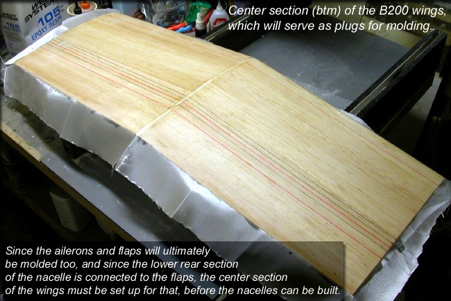
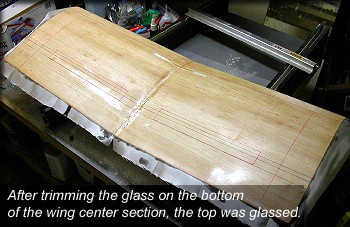
The wing center section must be assembled to use as a reference when making the nacelle parts, so that's the next step. (above) The center section will ultimately become the plug from which molds will be made.
Those beautiful Raisbeck nacelles deserve some thought.The motor mount extends far forward of the wing yet must still be strong enough, without allowing excess vibration. The inlet ducts will be scale in appearance, and provide air for engine cooling, and the large turbine exhaust tubes will function as the outlet for the engine cooling air. The front part of each cowling will be removable, in a scale manner, for easy engine and fuel system access. The rear portion of the nacelles contains the (Raisbeck) wing locker, and attaches at the rear bottom, to the inboard flap, so it must be hinged. It must be clean aerodynamically, when shut. They also contain the main gear door mechanisms. Actual mechanical support for the landing gear is via the wing spar. |
|
|
One of the most challenging parts of the nacelle design is that although they're the same shape, right and left, the points where the wings pass through is different on each side. (bigger wing section inboard, smaller one outboard) The wing dihedral also means that the height of those points is different on each side. That's why I'm using the model's wings to aid in the design. |
|
|
|
|
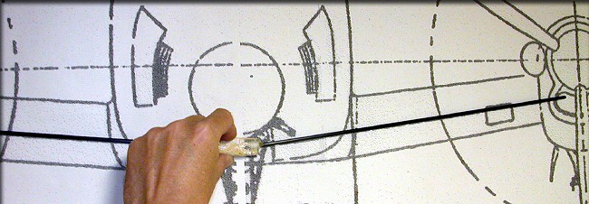
I made a simple dihedral guide by epoxying two carbon rods into a hardwood block, checked against the plans.
The wing center section test-fit to the fuselage
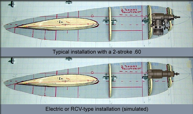
You can see why I prefer electric power. It allows a much more scale installation.
The cylinder of any 2-stroke or 4-stroke (Aside from possibly an RCV) will show through the inlet duct.
That's 109 inches of wing you're looking at.
Click the "The Plugs 02" link below to continue.