Create the plans
Published measurements from Lockheed Martin match with the Revell model. Here, using a little spreadsheet, I've made some rough guesses about the final weight of the model, to help me select a scale. Ducted fan and turbine flyers would be especially interested in the fuselage size, for example, to insure that the engine and fuel will fit. For the purpose of this example, I'll choose 1/10th scale. That fits with the "Eliminator 2" sport jet I'm designing for prop power, and although I'm not making a scale F/A-22, I'll incorporate some of the shapes in my model. Since the physical size of the plastic model is 1/48th, that means that I'll multiply all measurements of the slices by 4.8 to get 1/10th scale. Warning: Disregard the bottom half of the specs here... They are left over dimensions from the YF-22, which I haven't corrected yet. The Revell model is a lot closer than some of those numbers look, and so at some point, I'll correct and refine all these numbers.
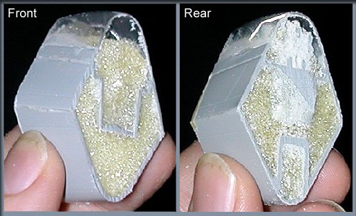
There's a lot more information in these slices than an exterior outline.
Looking at the front of the section above, note that as you trace these, you could also mark the canopy area, canopy frame area, and the outline of the front edges of the cockpit tub. Looking at the rear of this section shows the same information, as well as the outline of the nose gear bay. I'll be tracing these, but an alternative method occured to me, which is even simpler. I believe you could take these small sections and use an ink pad, (the kind used for rubber stamps) to wet the part, then simply "stamp" it onto graph paper. So, on to the graph paper...
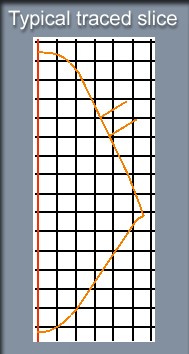
Here's a photo of a typical slice of the model, traced on graph paper. (enhanced a bit, for clarity) The red centerline will be used later to produce a mirror image of the slice, so that the "left/right" errors are eliminated. The two slashes near the top of this image indicate the position of the canopy frame.
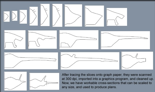
Each of the slices was traced on graph paper, scanned at 300 dpi, then imported into a graphics program and cleaned up, removing eraser marks, pencil lines, etc.. Now, all 18 sections are ready to be scaled to any size required, and you can make plans. Note than since we had physical sections to trace, I was able to include the wing and tail parts, as well as landing gear and weapons bays. These are handy when the physical model is planned. Simply enlarge the 3-views to the scale you want, then place these cross-sections in their appropriate positions. Remember that we made these slices at a uniform interval of 3/4", so just scale that number up to match the size you've chosen, and make your plans. (See below)

Here's the example you'd use if scaling up to 1/10th.
There you have it. A few days of simple work, with a plastic display model and some graph paper, and you can create an accurate shape for virtually any model, including one of your own design. Have fun!
Choose your model | Measure & Cut | Create the plans