Measure & Cut
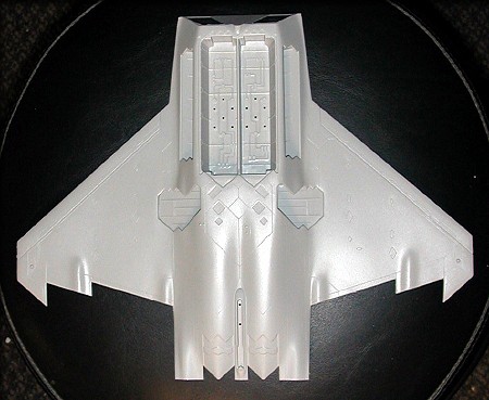
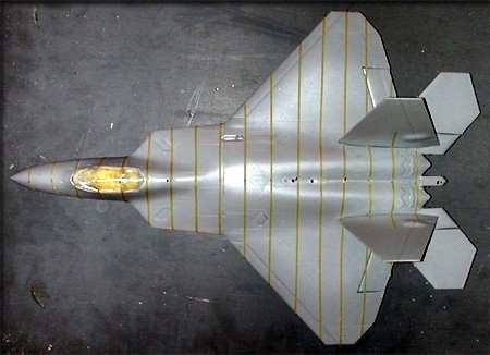
Here's a look at the bottom of the fuselage, showing all the openings for landing gear and weapons bays.
Since the aim of this project is to produce cross-sections of the airframe, I won't be installing any weapons or landing gear parts. The doors could just be glued on, but when the model is later sliced up, those parts are likely to fall apart. So, I'll be using some very small amounts of urethane foam to fill those areas, before gluing on the doors. I'm using a 2 lb. density, "mix and pour" urethane foam (West Systems) to solidify this model. That will help keep all the parts together, and when it's sliced up, the slices won't be so fragile.
Dispelling an old wives tale...
There are those who say that filling a plastic or fiberglass model with urethane foam will create tremendous heat and pressure, and distort the part. Actually, it's very easy to use this inexpensive material, with just a little common sense. Pressure and heat problems can both be avoided by simply not using too much at once, and allowing some openings for the excess to escape. In this case, the 1/48th scale of the model makes this issue completely mute. I used about 1/4 ounce of mixed urethane to fill the nose section below, poured all at once. No heat , pressure, or distortion problems. If you add as much foam as possible before assembling the kit, you avoid any unexpected heat and expansion problems.
Remember... The more foam you mix in a single batch, the faster it will kick off and expand. It can be a little messy, since the exact amount required is sometimes hard to predict, so use small amounts at first. Once cured, the foam is easily picked off any exterior surfaces of the plastic model. So, try and be neat, but don't let this spook you.
|
|
|
|
A little foam expands out the bottom rear. |
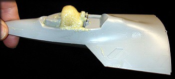
A little foam also came through the cockpit. |
|
|
|
|
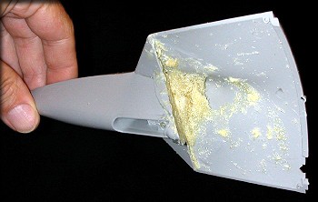
Here I've trimmed away most of the excess foam. |
I'll make sure the cockpit area is filled before adding the canopy. |
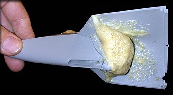
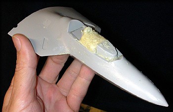
Because the nose section is nearly sealed off once it's joined with the fuselage bottom, I chose to fill it separately, first. I propped the nose section up vertically, with it's nose down. Then I mixed about 1/4 oz. of urethane foam, and poured it carefully into the rear of the nose section. If foam starts to expand outside where you want it, use a paper towel or tissue to wipe it away before it solidifies. Don't worry about every speck though, because once it's cured, it's very easy to either cut away (interior areas) with an X-Acto knife, or to simply pick it away (exterior areas) with your fingers. Test fit these sub-assemblies together, to make sure you've removed enough foam to eliminate interference, but are leaving as much foam as possible, for strength.
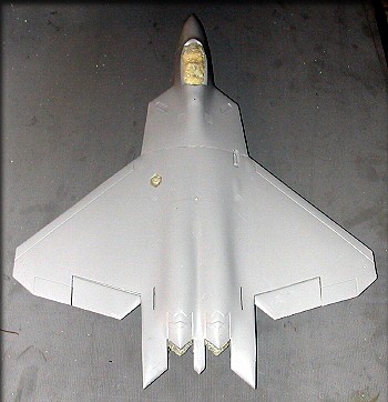
All landing gear and weapons bays, and the cockpit area are filled with foam.
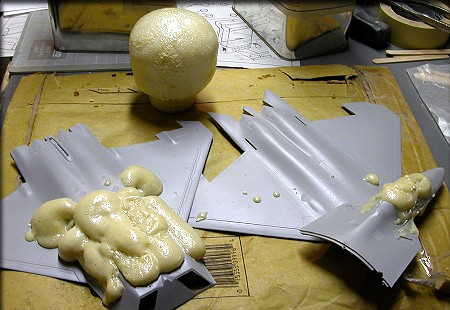
Here's how far 1/4 ounce of mixed foam will go...
I filled all the places I needed to fill, and then set the (2 oz.) cup down, because it was overflowing. That "mushroom" in the background shows how much this foam expands. Again, don't let this look worry you. The excess foam is easily removed after it's cured, and it sands very easily.
|
|
|
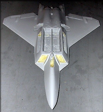
Here's the fuselage assembly after some trimming of the foam.
I picked away at the excess foam in each fuselage half, until I had removed just enough to join the two fuselage halves. During that process, I realized that because of the particular way this model is molded, filling up the weapons bays and landing gear bays is not necessary. (Those areas are molded integrally into the bottom fuselage half.) So, proving what I said above, that foam was easily removed from those areas, using only my fingers. If you think about how these cross-sections will be used, it actually isn't even necessary to glue the doors over these openings. If I do it, it will only be "for show".
After assembly, the model is taped for slicing.
I wanted all the slices to be at uniform intervals, and in this case I randomly chose to make a slice every 3/4". That results in 18 slices, which is adequate to produce a nice plug. I decided to attach the vertical and horizontal tail fins, just to see if I could slice through them without their falling apart. (Since I bought two of these kits, I always have the other one for reference if anything gets damaged.)
I was surprised and pleased that most of the tail parts stayed attached during the slicing process.
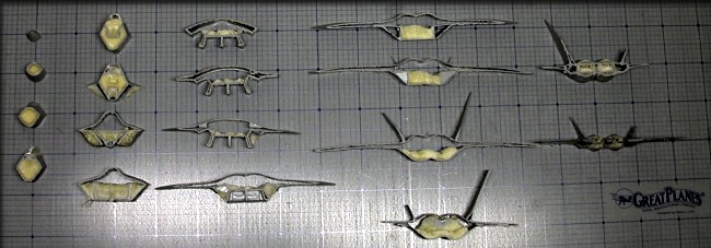
A few minutes with a band saw yeilded all these very useful cross-sections. Next, they wll be traced onto graph paper, and scanned into the computer. The graph paper lines insure that the sections are perfectly vertical. Once these parts are scanned, they can be scaled to any size, and work can begin on the plans.
Click the "Create the plans" link below to continue.
Choose your model | Measure & Cut | Create the plans