J-46 Trainer/STOL Type
Design Overview
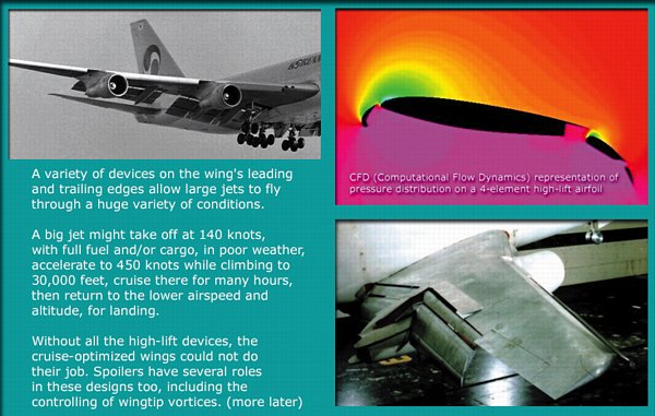
There are times that I'd like to be able to fly a fast aerobatic model more slowly, with full control, as well as takeoff and land more slowly. It would also be nice to have a model that could carry more payload, and still be able to take off and land slowly, in a small space. Full-scale aircraft accomplish this by using a variety of high-lift devices, including flaps on the trailing edge of the wing, and various modifications, (both fixed and moveable) to the leading edge of the wing. Today, many new aircraft are being designed with thrust vectoring too, but this project won't include that feature. Here are a few images that show some of the popular high-lift devices in use today.
If you're interested in high lift devices for RC models, you can help! I've created a separate set of pages devoted to these devices, and how to apply them to models, here. If you contribute links, images, or articles, (by emailing them to me) I will add them to the site and credit you as the author.

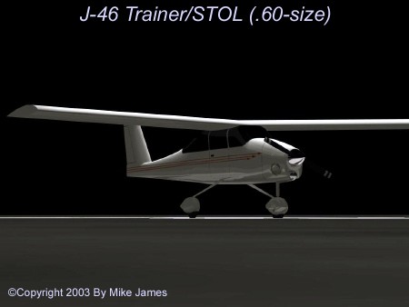
I've settled on some design parameters for these tests. The test model will be a moderate size (.60) airframe with a high-mounted wing, T-tail, and conventional (taildragger) landing gear. This configuration will let me easily switch from one wing to another, to try several different high-lift setups. Each wing set will have a chord of 12 inches, and have a span of 68 inches, giving 816 square inches of wing area. It will have a low-drag fuselage (integral vertical fin) molded from fiberglass, with balsa-sheeted foam wings and horizontal stabilizer. The final model will offer the option of tricycle landing gear, for use as a trainer.
In the image above, you may notice that the CAD model has a very short span. I felt that the only fair test of the performance gained by using these devices would be on a highly loaded test platform. So, the first test flights will be with the version above, which is a 40-inch span, 580 square inch wing. Once the high-lift devices are proven, the final version will have the higher aspect ratio mentioned in the first paragraph above.
Visit the Kronus Robotics page to learn how to modify servos for use as jackscrew drivers for flaps.
Giving credit where it's due, I must acknowledge that this is my expansion of some marvelous work done by Andy Lennon. His book, "The Basics of RC Model Aircraft Design", (ISBN: 0-911295-40-2) is available through Air Age Publishing. Andy has done a great job collecting airfoil and other performance data, as well as designing many successful airplane models. I've had many phone conversations with him, mailed information back and forth, and sought his advice on more than one occasion. His work forms a solid base for these tests. Thank you, Andy Lennon!
Oliver Wilson, another highly-skilled and talented designer and builder, has also helped with advice on airfoils, on more than one occasion. Ollie knows a tremendous amount about differences in airfoils with respect to Reynolds number effects, and I trust his judgment completely. Thank you, Ollie!
The first thing I discovered by doing some research, along with some experiments with paper cutouts, is that double-slotted Fowler flaps could be simulated quite well without complex linkages or radio setups. That was encouraging, because it meant that I could do a proof-of-concept model without spending a lot. Above are 5 images I created to prove the geometry, made into an animation.
From 0 degrees to 40 degrees, only the slot to the main flap is open, with the secondary flap actually creating the main flap slot. Once 50 degrees of flap is deployed, the secondary flap moves rearward and downward, and it's slot opens up. At first glance, it looks like the small secondary flap would be the hardest thing to fabricate, but I had some hardwood (airfoil-shaped) struts laying around from a previous kit. All that was required was a little shaping, to give them the camber you see in the images above.
The triangular piece above the flap outline is a spoiler...technically a "slot-lip aileron". Spoilers are effective for roll control in general, but once the flaps are deployed enough to create a slot, they actually become even more effective. When they raise, they not only cause the usual drag, but they open the flap slot, killing the effect of the slot on that side. That's why airliners use them, and I'm interested to see the results in a model.
The next step is to decide how I want to manipulate the leading edge. The choice of either slats or a droopable "leading edge flap" is yet to be decided, but I probably will select slats. It's early in this experiment... Stay tuned.
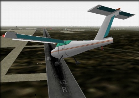
I've been flying this setup in the "X-Plane" simulator, and it's performing nicely. The version shown here has nearly full-span flaps, and uses spoilers for roll control. (and speedbrake) Here I've got single-slotted Fowler flaps at 40 degrees, slats & spoilers/speedbrake deployed, in a sideslip.
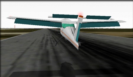
With the same devices as above deployed, the model can achieve a high angle of attack for sloooow landings.
Back to the Projects page